Cisco Packet Tracer · Enterprise Case Study

Enterprise network
troubleshooting,
done in the open.

Most networking portfolios show a clean diagram. This one shows what happened before it got clean — VLAN segmentation, router-on-a-stick, DHCP relay, trunking failures, native VLAN mismatches, and eight documented break-fix cycles.

Aurelian Financial Group came to me with a flat, undivided network and a business requirement for department segmentation. What followed was a full enterprise build: four VLANs, one router-on-a-stick, centralized DHCP relay, and a troubleshooting trail that turned every misconfiguration into a documented learning artifact.
0VLANs
0Network Nodes
0Issues Resolved
T2/3Diagnostics
100%DHCP Validated

The Brief

A fictional financial firm needed
a segmented, supportable network.

Aurelian Financial Group was modeled as a growing financial services company with Finance, HR, IT, and Management departments. The goal was to move from a flat network into a proper enterprise design with VLAN boundaries, centralized DHCP, routed inter-VLAN connectivity, and troubleshooting evidence strong enough to discuss in an interview. Built and validated entirely in Cisco Packet Tracer 8.x.

Cisco IOS 15.x Packet Tracer 8.x Cisco 2911 Router Cisco 3560-24PS Cisco 2960-24TT ×4 802.1Q Trunking Router-on-a-Stick DHCP Relay Extended ACL Port Security SSH Hardening STP Diagnosis

Business Impact

Designed around business risk,
not just network commands.

The network was modeled for a financial organization where segmentation, predictable addressing, and fast incident recovery matter. Every design decision maps to a real operational outcome.

Department Segmentation

Finance, HR, IT, and Management are separated into dedicated VLANs, reducing unnecessary broadcast traffic and creating clean policy enforcement boundaries between sensitive departments.

Centralized IP Management

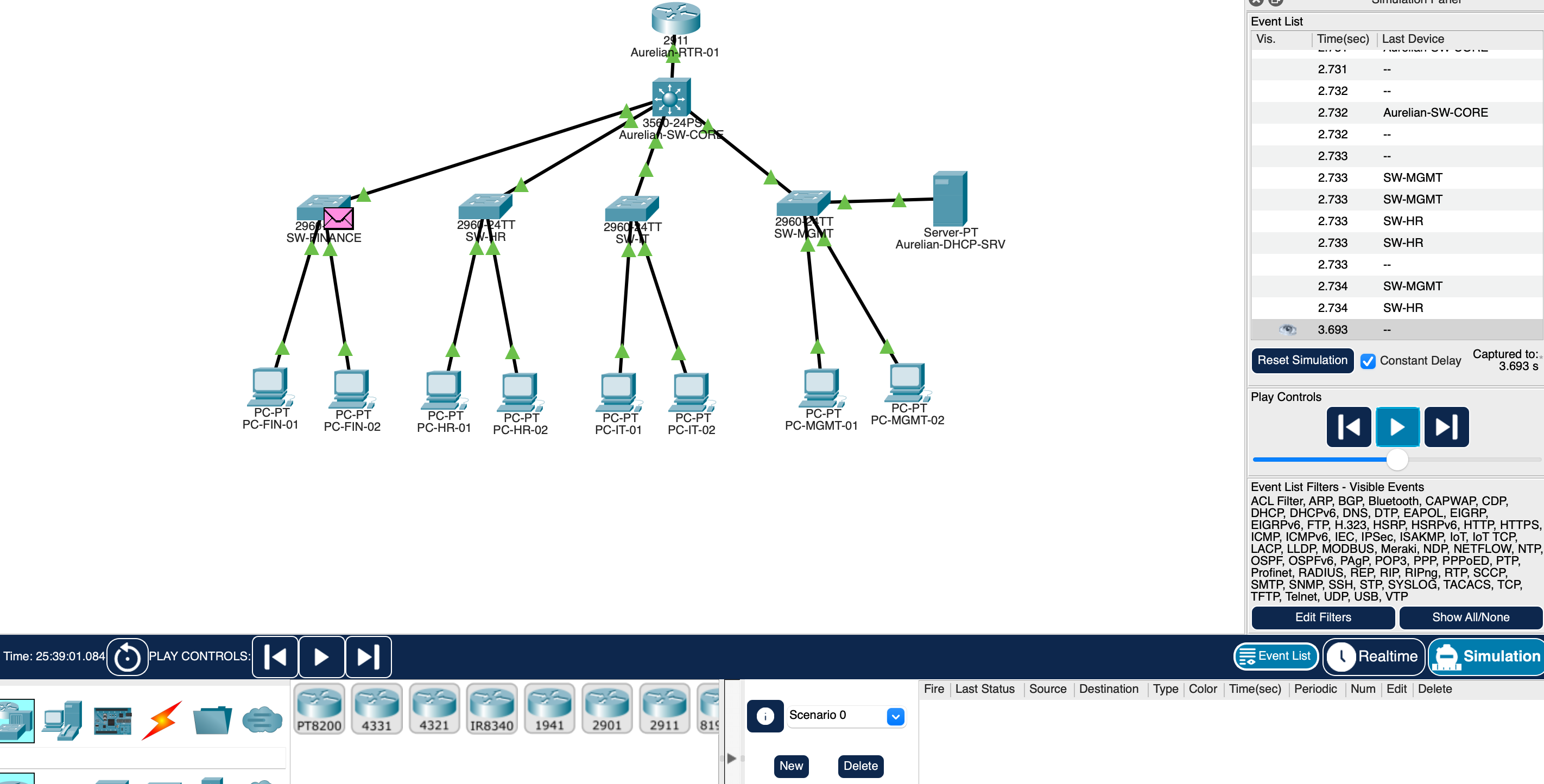
A single DHCP server in the Management VLAN simplifies address tracking and auditing. Router helper addresses relay broadcasts across VLAN boundaries — no per-segment server required.

Supportability First

Every config decision was validated with show commands, ping tests, and documented root-cause notes — so a support engineer can diagnose this environment under real pressure without guessing.


Network Architecture

Router-on-a-stick with
departmental VLAN segmentation.

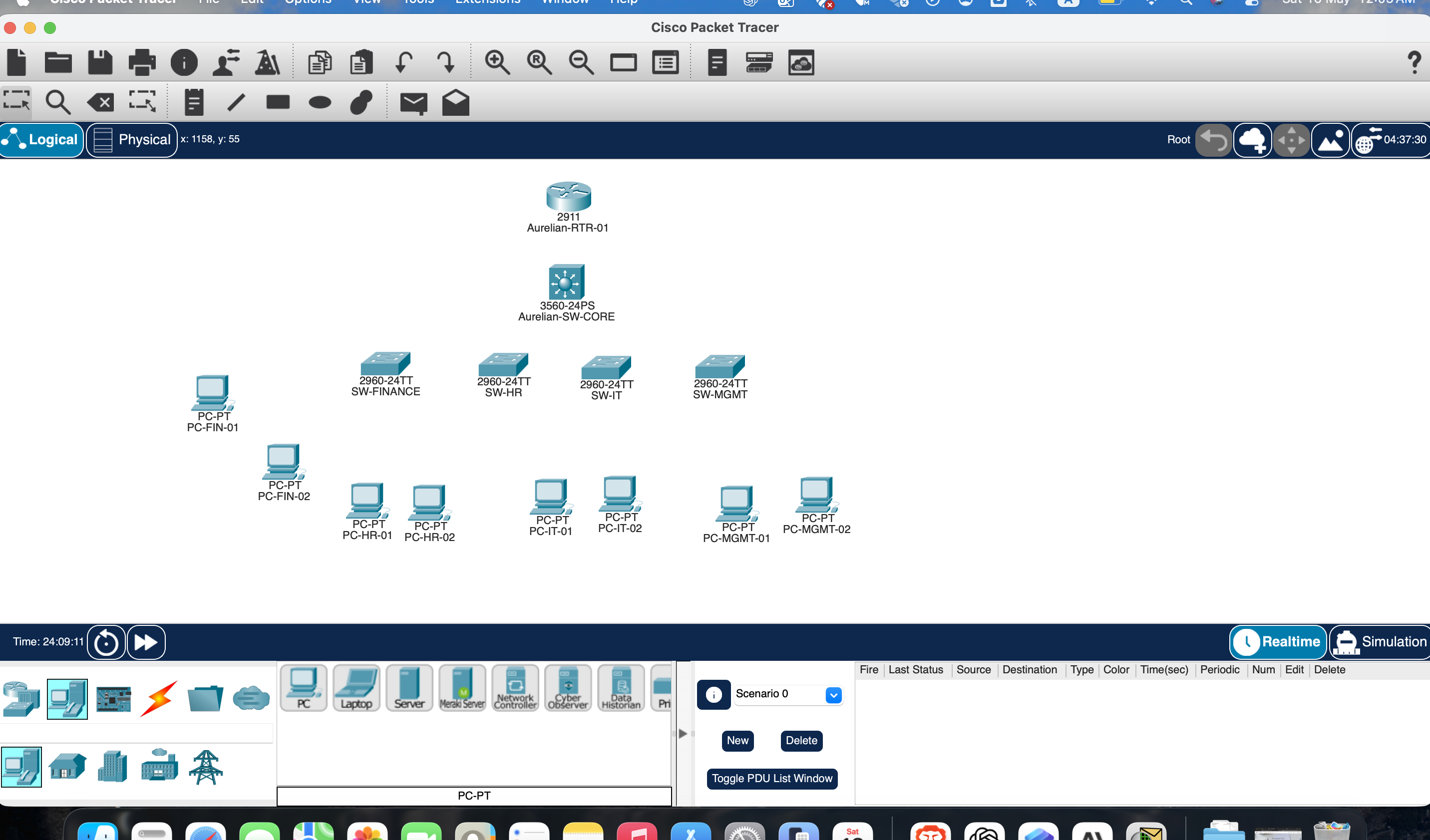
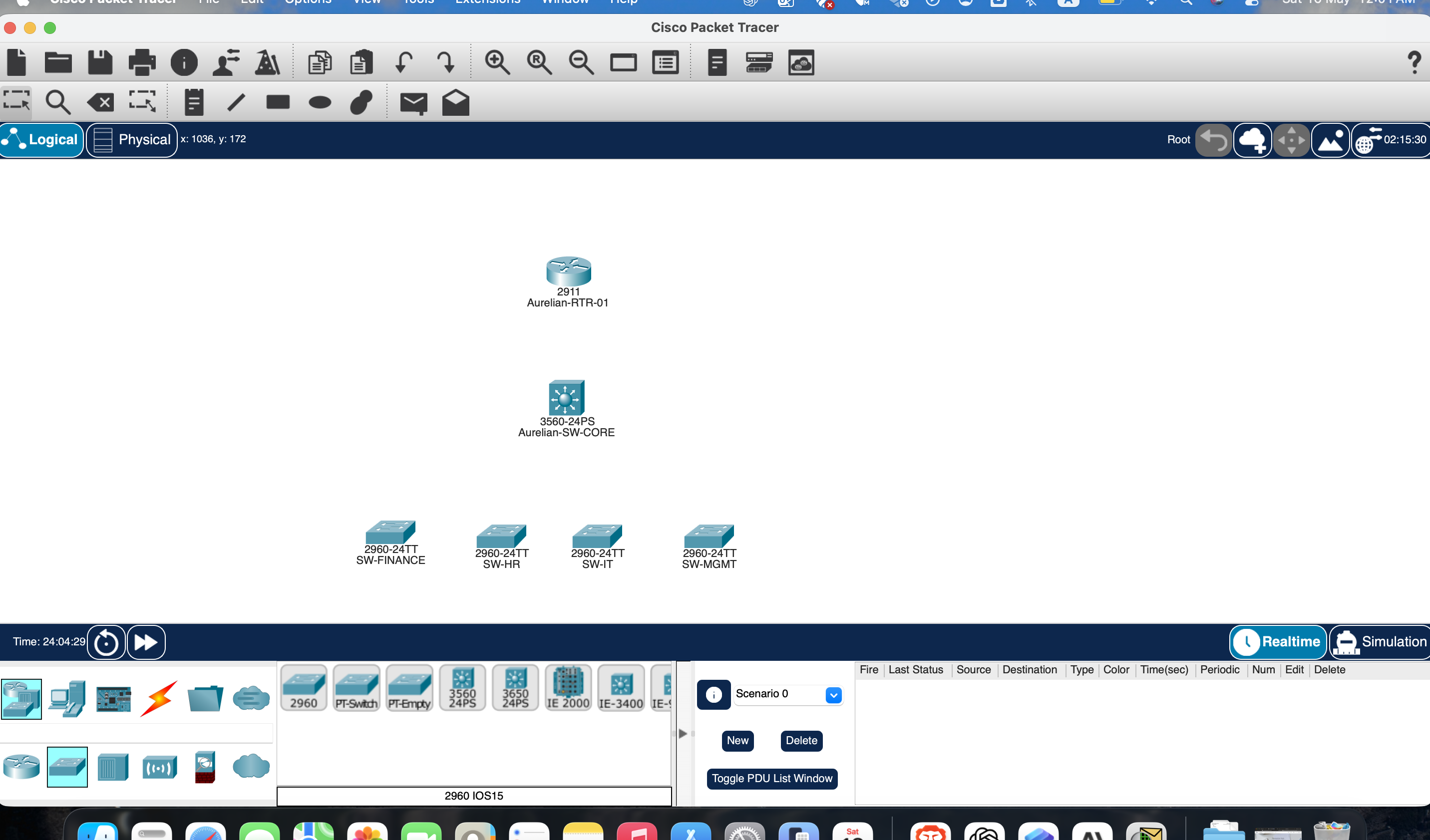
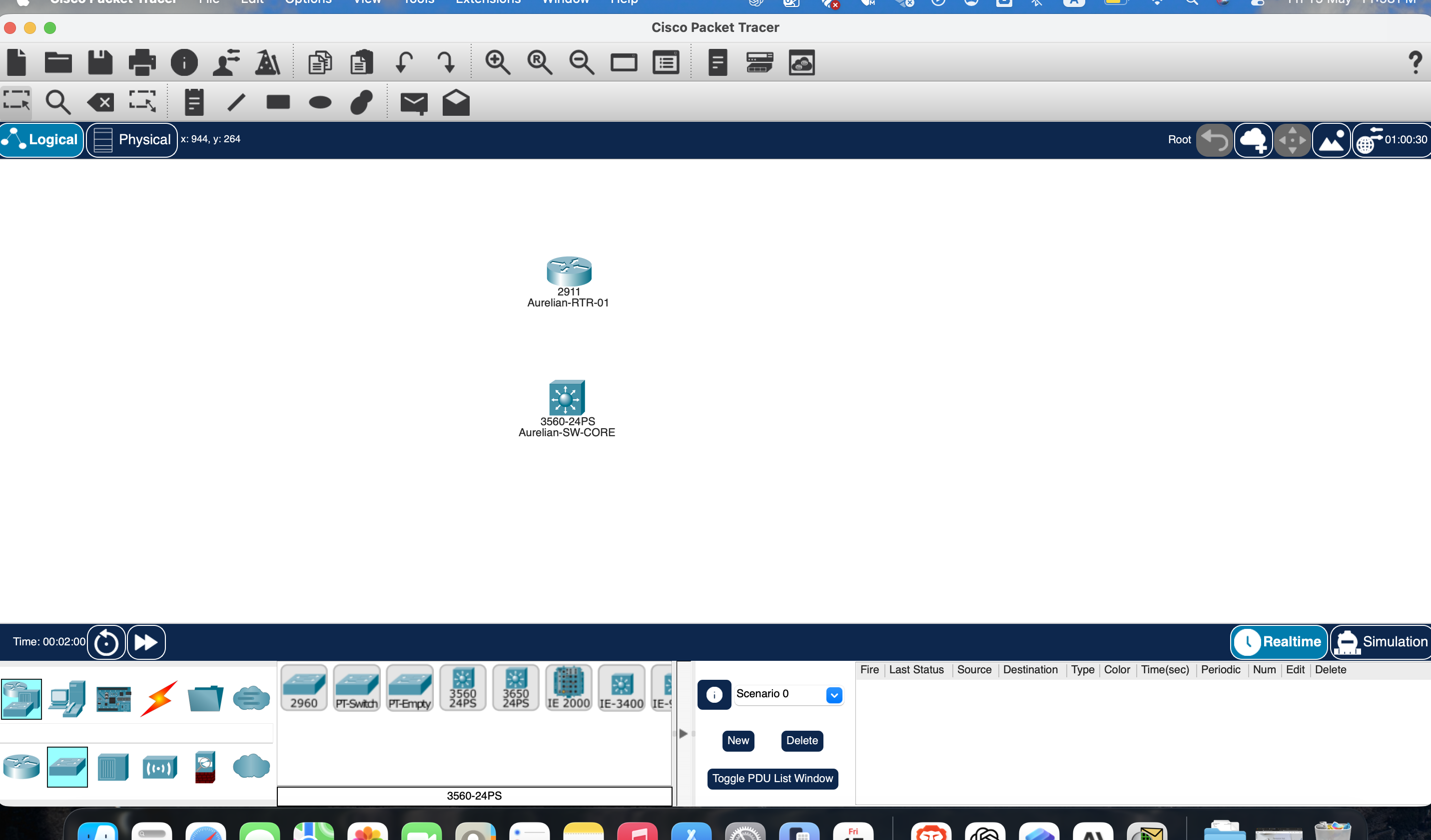
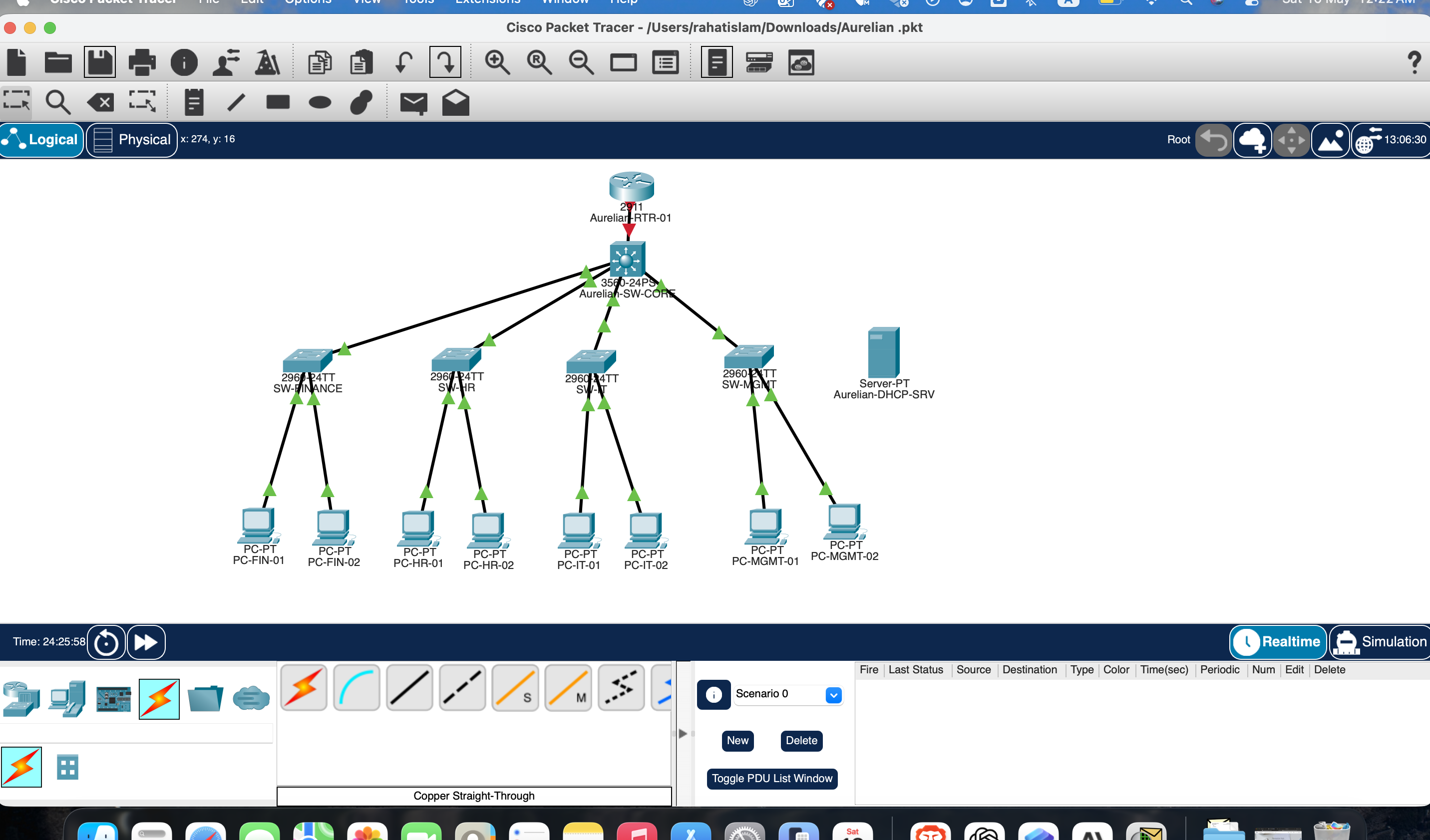
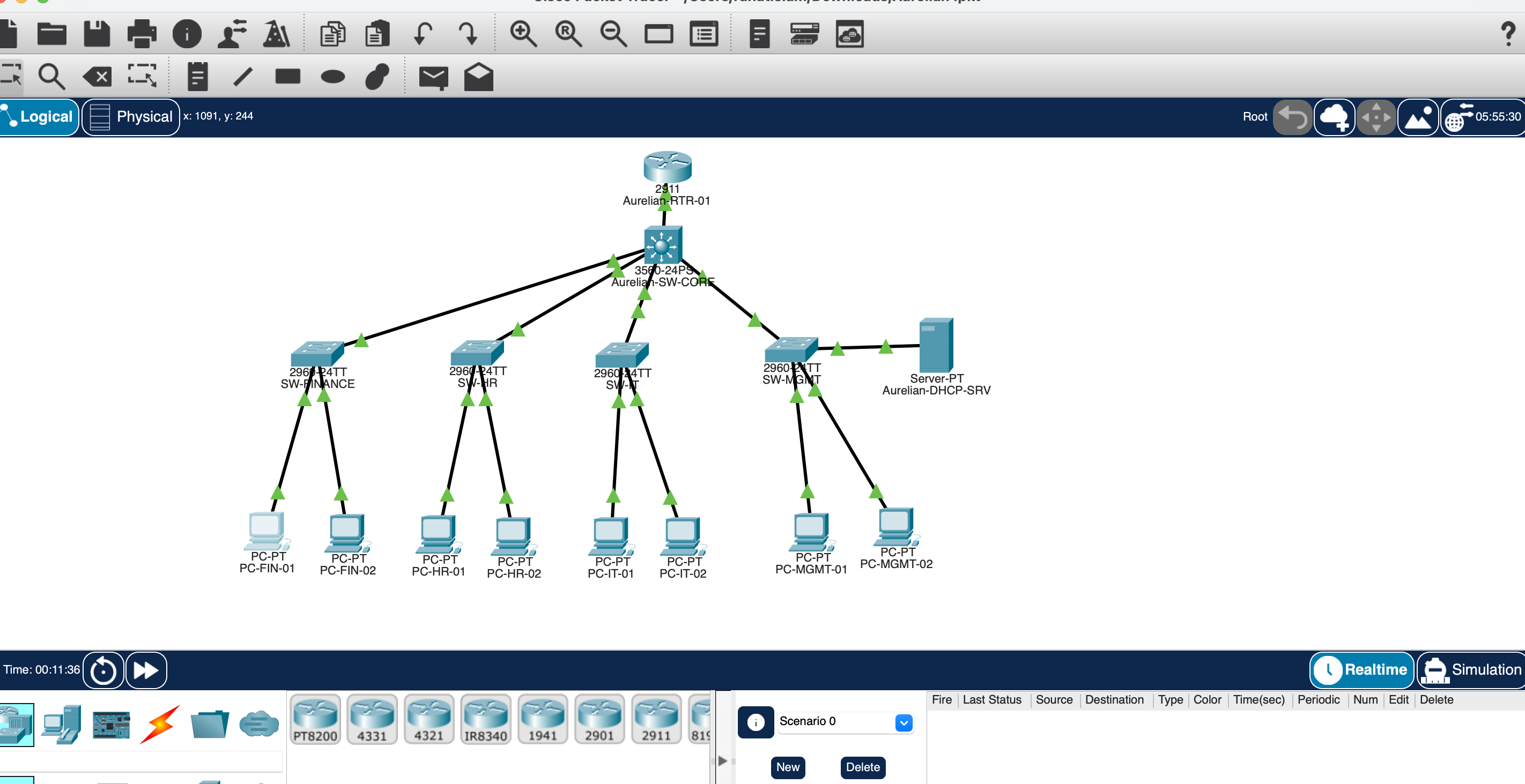
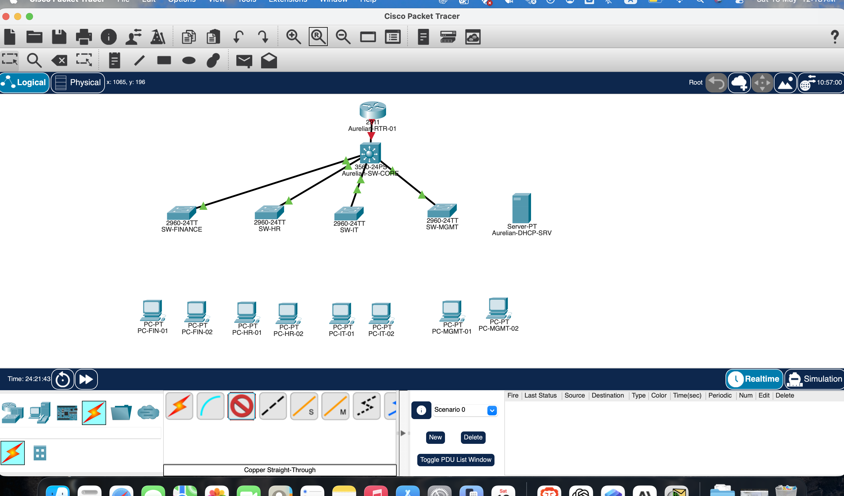
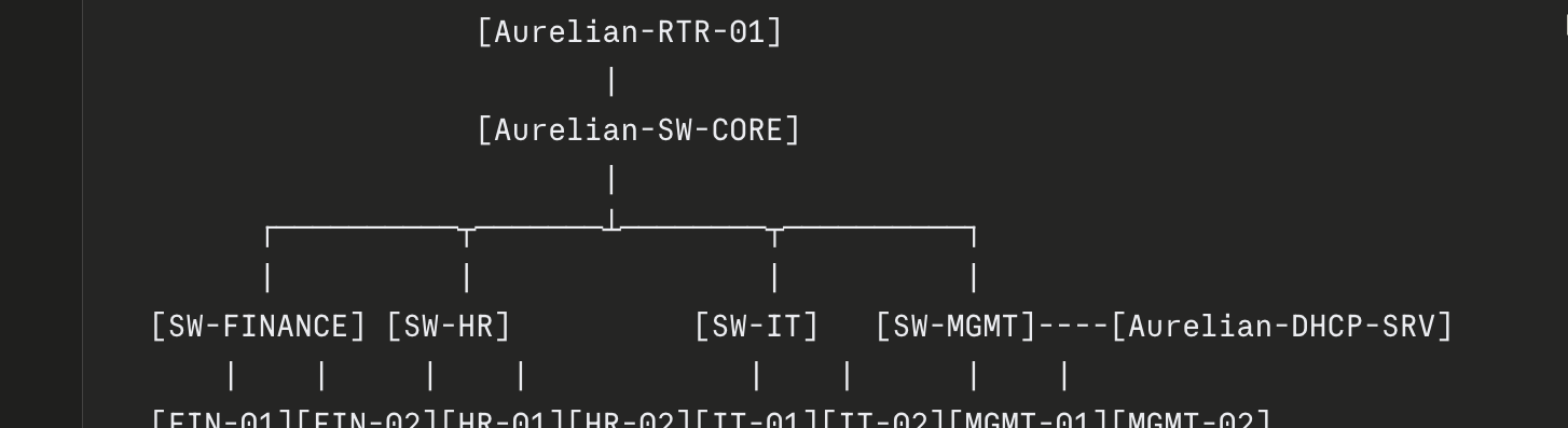
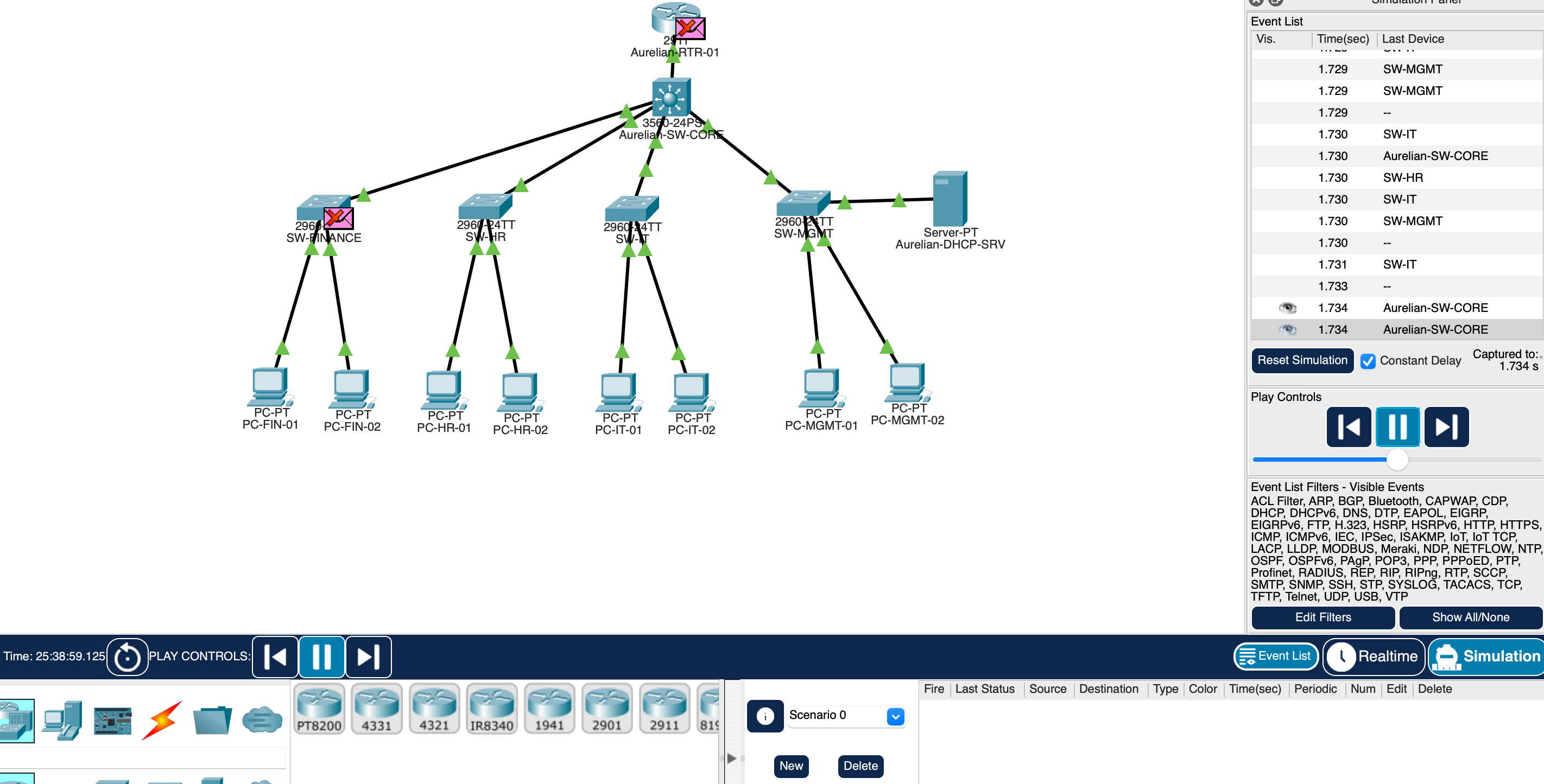
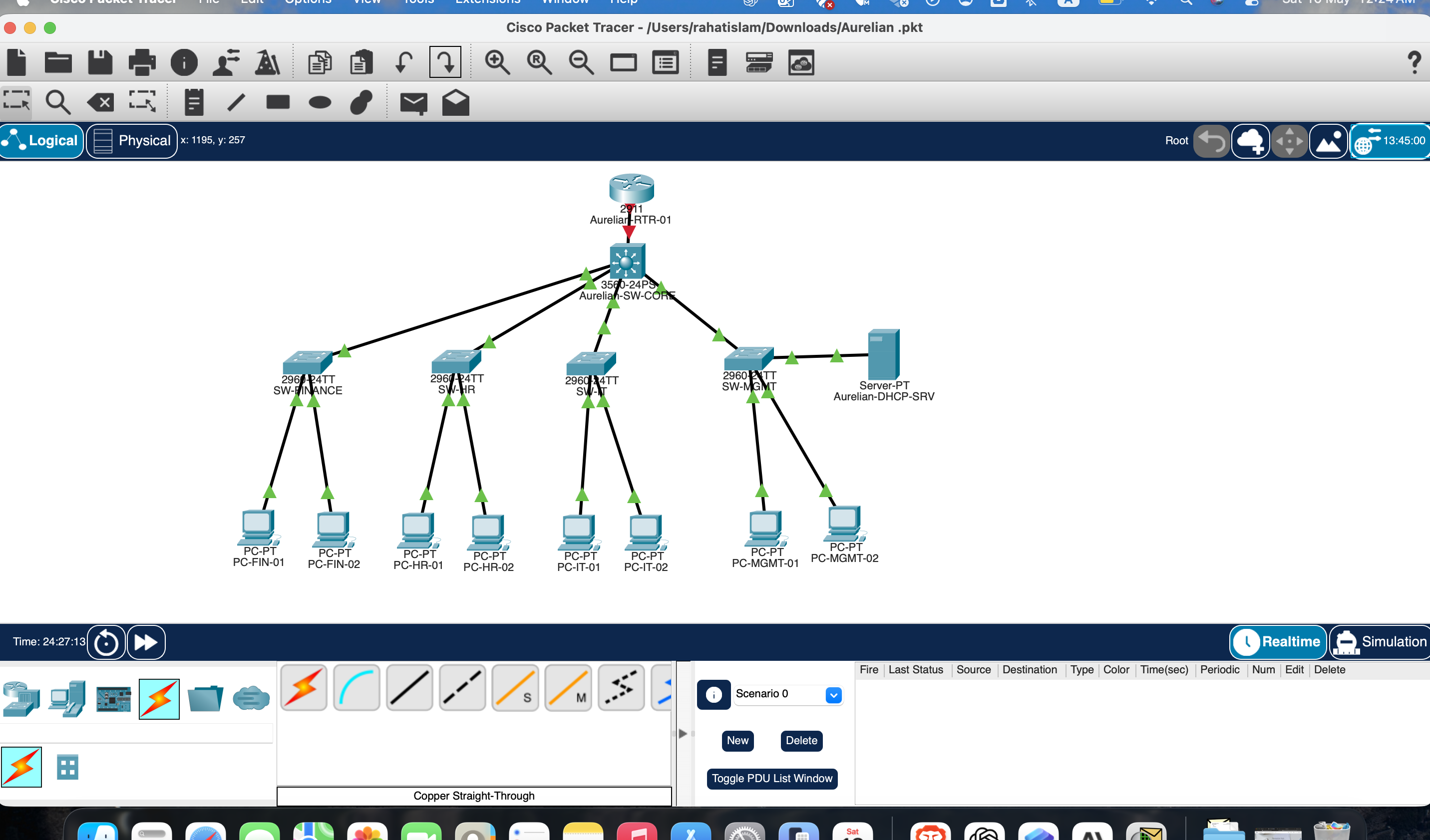
One Cisco 2911 router, one 3560-24PS core switch, four 2960 access switches, eight department PCs, and a centralized DHCP server — wired in a core/access model with 802.1Q trunking throughout.

VLAN 10
Finance
Subnet: 192.168.10.0/24
Gateway: 192.168.10.1
Switch: SW-FINANCE
Pool: FINANCE_POOL
VLAN 20
Human Resources
Subnet: 192.168.20.0/24
Gateway: 192.168.20.1
Switch: SW-HR
Pool: HR_POOL
VLAN 30
Information Technology
Subnet: 192.168.30.0/24
Gateway: 192.168.30.1
Switch: SW-IT
Pool: IT_POOL
VLAN 40
Management
Subnet: 192.168.40.0/24
Gateway: 192.168.40.1
Switch: SW-MGMT
DHCP Server: 192.168.40.2
DeviceModelRoleConnected To
R1Cisco 2911Router-on-a-Stick / DHCP RelayCore Switch Gi0/1
SW-CORECisco 3560-24PSCore switching / VLAN propagationR1 + 4 access switches
SW-FINANCECisco 2960-24TTFinance access layerCore + 2 PCs
SW-HRCisco 2960-24TTHR access layerCore + 2 PCs
SW-ITCisco 2960-24TTIT access layerCore + 2 PCs
SW-MGMTCisco 2960-24TTManagement + DHCP serverCore + DHCP server
DHCP-SRVGeneric ServerCentralized DHCP for all VLANsSW-MGMT Fa0/2

Architecture Decisions

Why this design was selected.

Every architecture choice maps to a real business or operational reason. Here is the reasoning behind the three key decisions.

Router-on-a-Stick

Chosen as a cost-effective method for inter-VLAN routing using subinterfaces with 802.1Q tagging. It is straightforward to explain in an interview, easy to validate with show commands, and common in smaller enterprise environments where a Layer 3 switch is not available.

Central DHCP in VLAN 40

A single DHCP server placed in the Management VLAN keeps address management centralized and auditable. The ip helper-address configuration demonstrates DHCP relay across routed VLAN boundaries — a Tier 2 diagnostic skill tested in interviews.

Core/Access Switch Model

Separating a central 3560 core from four 2960 access switches creates a cleaner operational model for troubleshooting: uplink issues stay at core, access-port issues stay at the edge. This also exposed the real-world 3560 encapsulation requirement early in the build.


Build Timeline

From blank topology to
routed enterprise network.

1

Physical topology and naming

Devices were placed, connected, and renamed to reflect a realistic enterprise environment. Router, core switch, four access switches, eight department PCs, and one centralized DHCP server. Physical cable endpoints were verified before any configuration was written.

2

VLANs and access port assignment

Finance, HR, IT, and Management VLANs were created on all switches. Access ports were assigned based on actual physical connections discovered during the build — not assumed from the intended design diagram.

3

802.1Q trunking and 3560 encapsulation

Trunk links were configured across all uplinks. The 3560 core required explicit switchport trunk encapsulation dot1q before trunk mode could be set — a known hardware difference from the 2960 that caused the first documented issue.

IOS interface Fa0/1
switchport trunk encapsulation dot1q
switchport mode trunk
switchport trunk native vlan 1
4

Router subinterfaces and DHCP relay

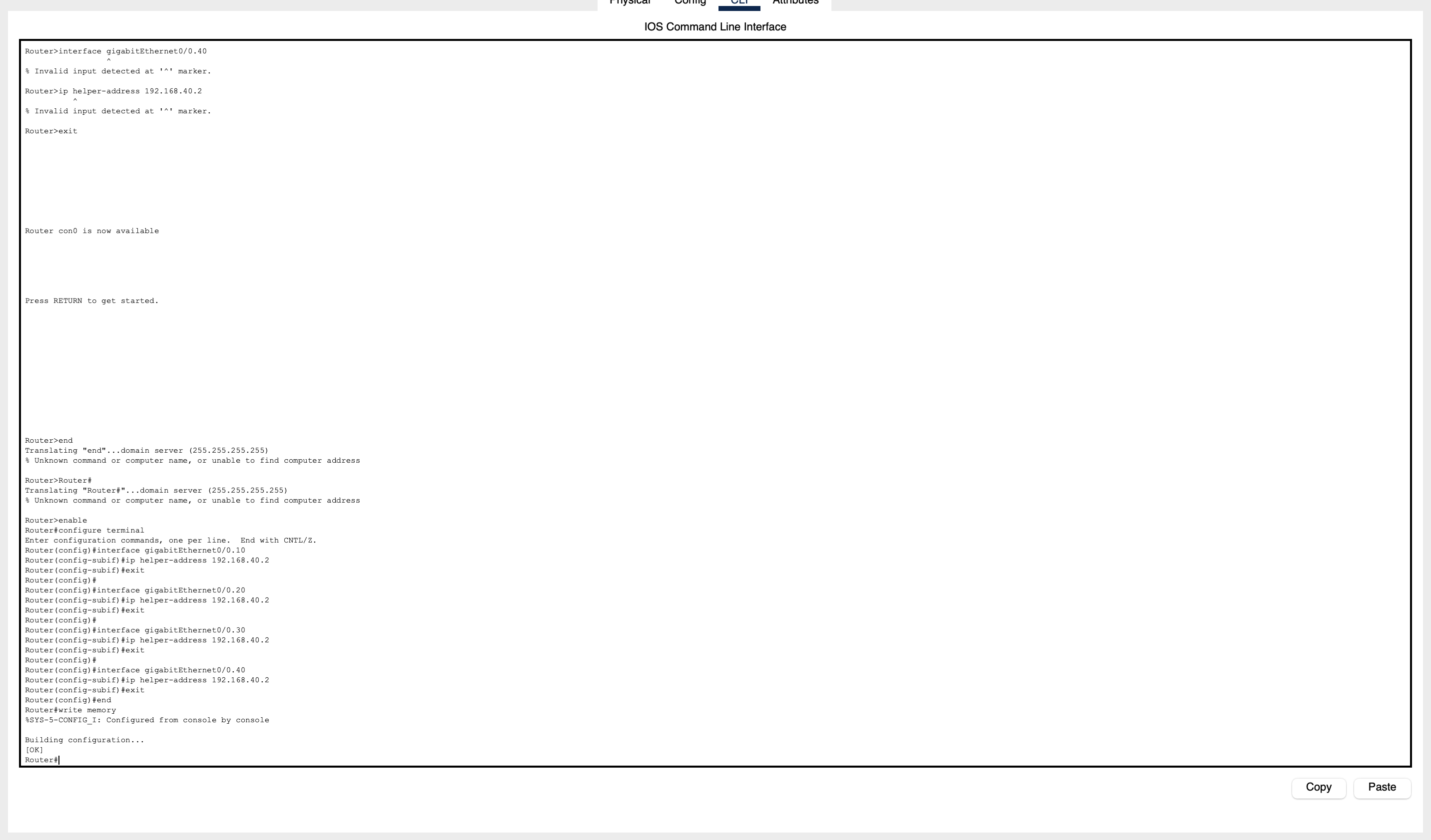
Router-on-a-Stick subinterfaces were built for each VLAN with dot1Q encapsulation, gateway IPs, and DHCP helper addresses pointing to the centralized server at 192.168.40.2.

IOS interface GigabitEthernet0/0.10
encapsulation dot1Q 10
ip address 192.168.10.1 255.255.255.0
ip helper-address 192.168.40.2
5

DHCP server configuration and pool validation

Four DHCP pools were configured on the server: FINANCE_POOL, HR_POOL, IT_POOL, and MGMT_POOL. The server was assigned static IP 192.168.40.2. Packet Tracer's default serverPool was discovered and neutralized after it conflicted with MGMT_POOL during validation.

6

Break-fix, validation, and config save

All eight documented issues were diagnosed and resolved. Final state was validated with ping tests, DHCP lease verification, and show command outputs across every segment. Configs saved with write memory and exported to the repository.


Operational Workflow

How every fault was
diagnosed — in order.

The troubleshooting process followed a layered operations path. No guessing, no random config changes. Every step was deliberate and the output of each step determined the next action.

01
Observe

Identify the visible symptom: APIPA address, failed ping, missing gateway, CDP mismatch warning, or STP inconsistency flag.

02
Physical

Verify actual cable endpoints and port connections before touching any config. Never assume the topology matches the diagram.

03
Layer 2

Validate VLAN membership, access-port state, trunk mode, native VLAN, and allowed VLANs on both sides of every link.

04
Layer 3

Confirm router subinterfaces are up/up, gateway IPs are correct, and DHCP relay helper addresses are applied to the right interfaces.

05
DHCP Server

Verify pool configuration, static server IP, correct mask, gateway, and DNS. Check for conflicting pools that may win the lease race.

06
Test

Renew the client lease with ipconfig /renew (or PC DHCP toggle), run pings, and confirm addressing matches the expected pool range.

07
Document

Record symptom, root cause, commands used, fix applied, and confirmed result. Every issue in this case study follows this format.

08
Save

Commit working configs with write memory. Export final configs to the repository so the environment is reproducible.


Break-Fix Log

Eight issues. Every one
documented in STAR format.

The strongest part of this project is not the final topology — it is the troubleshooting trail. Each issue is documented with the full Situation → Task → Action → Result cycle that a Tier 2/3 support engineer uses in real incident notes.

01
High Severity
3560 Core Switch — Trunk Mode Silently Fails Without Explicit Encapsulation
Situation
Access switches showed connected links to the core and VLANs appeared to be created, but VLAN traffic was not forwarding across the network. show interfaces trunk on SW-CORE returned no active trunk ports despite trunk mode being configured.
Task
Identify why trunking was silently failing on the 3560 core switch when the same commands functioned correctly on the 2960 access switches.
Action
Ran show interfaces trunk and show interfaces status to confirm the trunk state. Identified that the Cisco 3560-24PS requires explicit switchport trunk encapsulation dot1q before switchport mode trunk is accepted — unlike the 2960, which defaults to dot1Q. Applied the encapsulation command to all uplink ports on SW-CORE.
Result
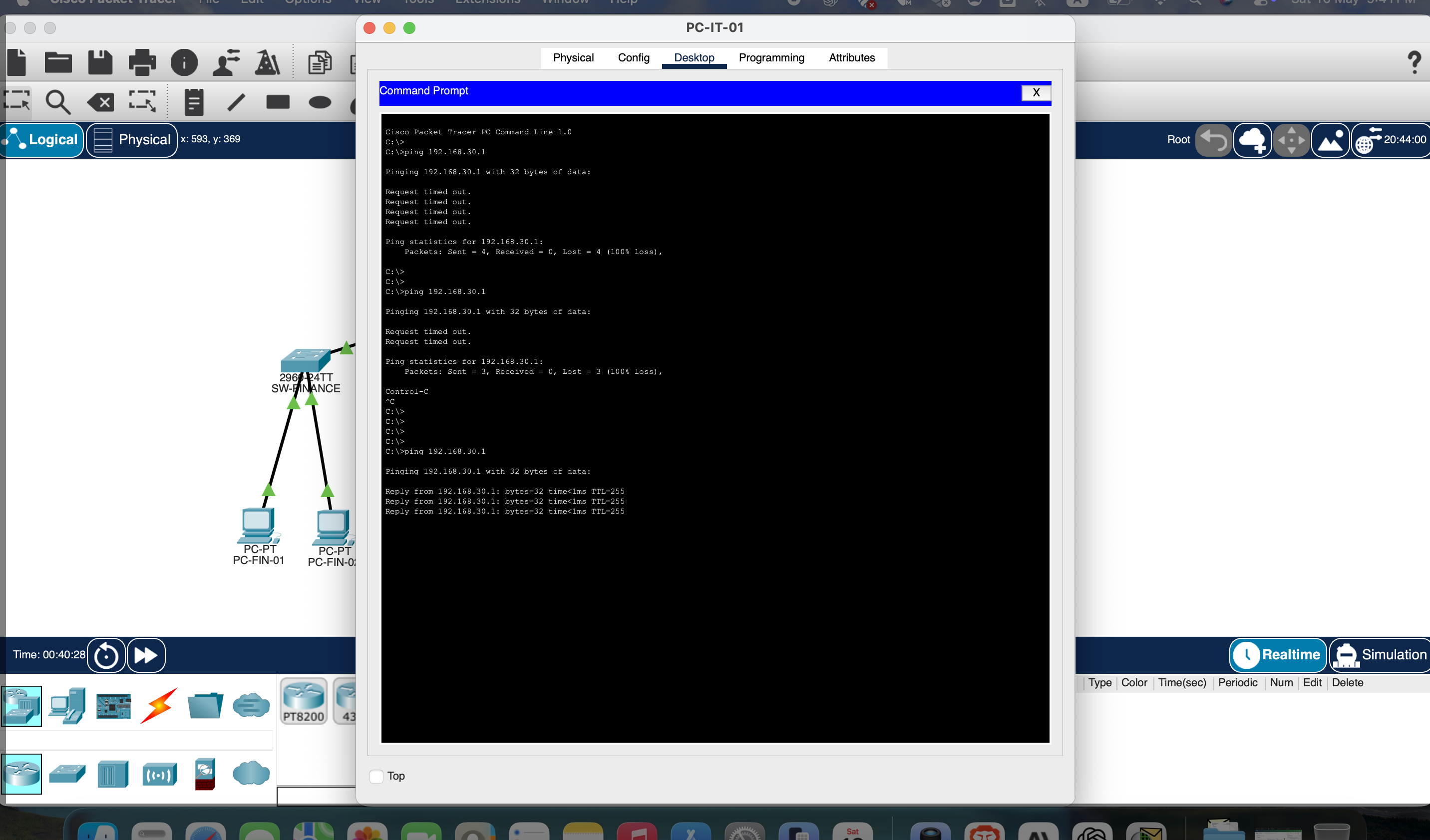
All four VLANs appeared immediately in the trunk forwarding table. VLAN traffic began propagating correctly to all access switches. This was the root blocker for the entire network build.
02
High Severity
SW-MGMT Uplink Configured as Access Port — CDP Mismatch and STP Inconsistency
Situation
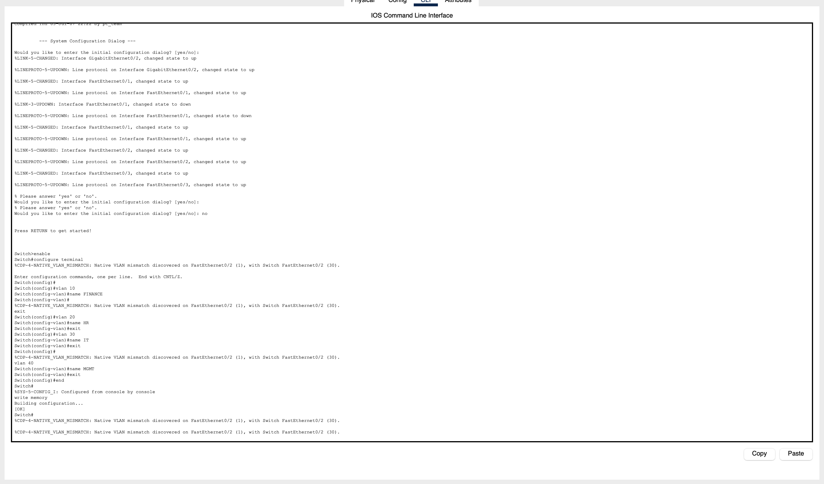
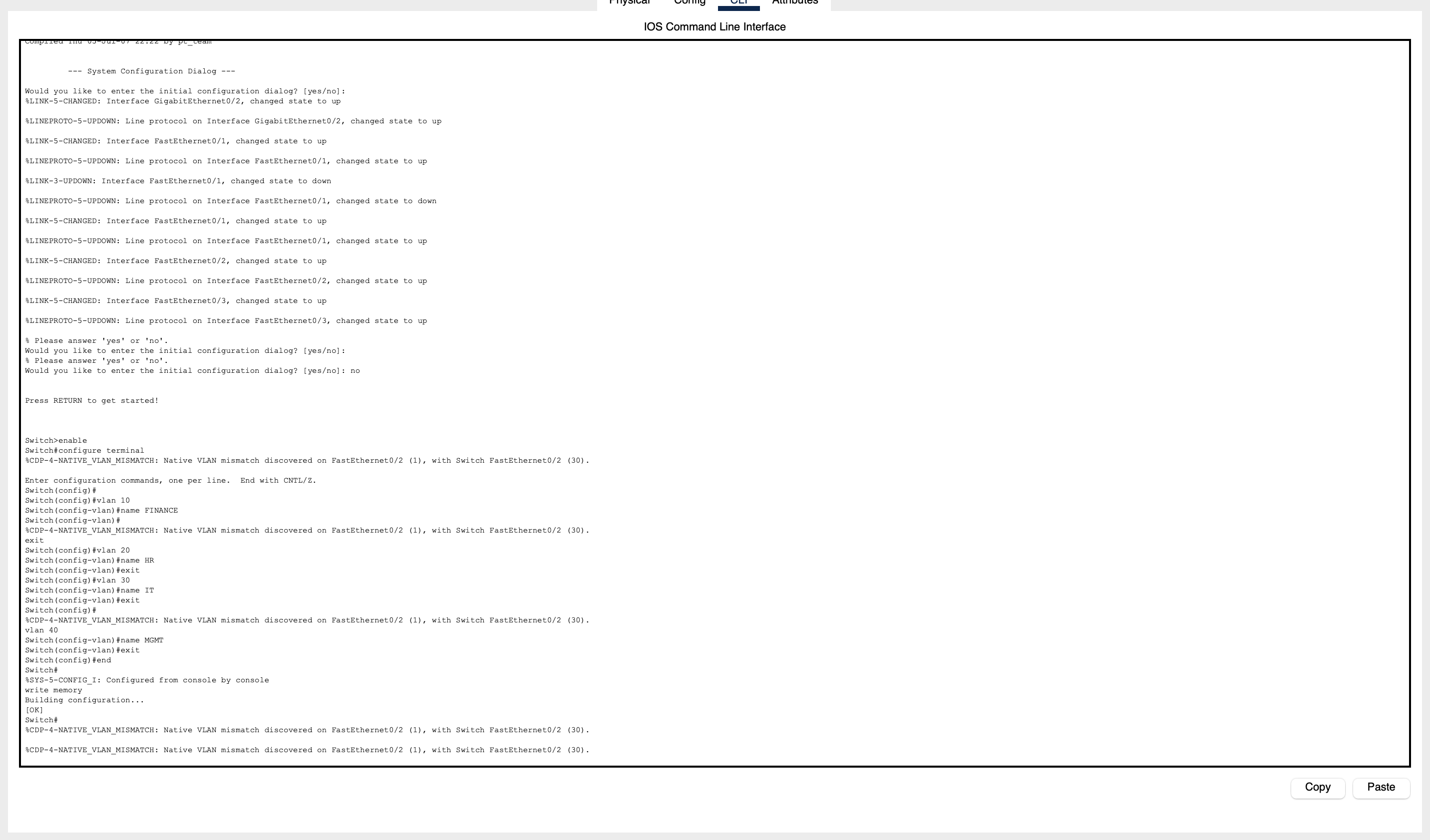
SW-MGMT Fa0/3 — an uplink port to the core switch — was mistakenly configured as an access port in VLAN 40. This triggered persistent CDP native VLAN mismatch warnings and caused STP to flag the port as inconsistent. The DHCP server appeared healthy locally but the router could not relay through it.
Task
Restore correct trunk configuration on the uplink without disrupting the DHCP server connection on Fa0/2.
Action
Used show interfaces status to identify Fa0/3 in access mode. Compared CDP output (show cdp neighbors detail) against the physical topology to confirm which port was the actual uplink. Applied switchport mode trunk and switchport trunk native vlan 1 to Fa0/3. Left Fa0/2 as access VLAN 40 for the DHCP server.
Result
CDP warnings cleared immediately. STP inconsistency resolved. The router could now relay DHCP requests through the restored trunk path to the DHCP server.
03
Medium Severity
Native VLAN Mismatch on SW-IT — Residual Misconfiguration After Core Fix
Situation
After correcting the core switch trunking, persistent CDP native VLAN mismatch messages continued on the SW-IT uplink. The core side was set to native VLAN 1 but SW-IT had native VLAN 30 leftover from an earlier misconfiguration attempt.
Task
Eliminate the mismatch by aligning native VLAN on both ends of the trunk without disrupting IT VLAN 30 access traffic.
Action
Ran show interfaces trunk on both SW-CORE and SW-IT. Confirmed the mismatch — one side native VLAN 1, the other native VLAN 30. Applied switchport trunk native vlan 1 to the uplink port on SW-IT. Verified both sides now matched.
Result
CDP mismatch warnings on SW-IT cleared. Native VLAN alignment confirmed across all four access switch uplinks. No impact to IT VLAN access traffic.
04
High Severity
PCs Physically Wired to Wrong Ports — APIPA Persists Despite Correct VLAN Config
Situation
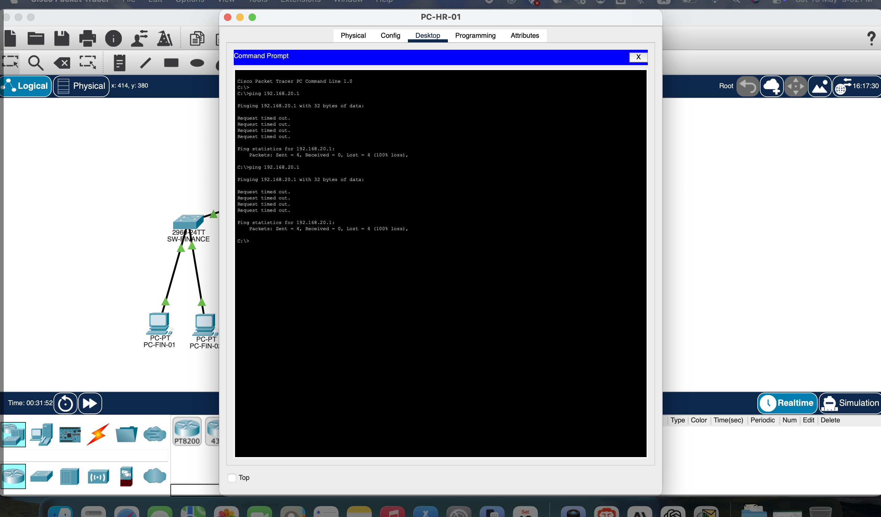
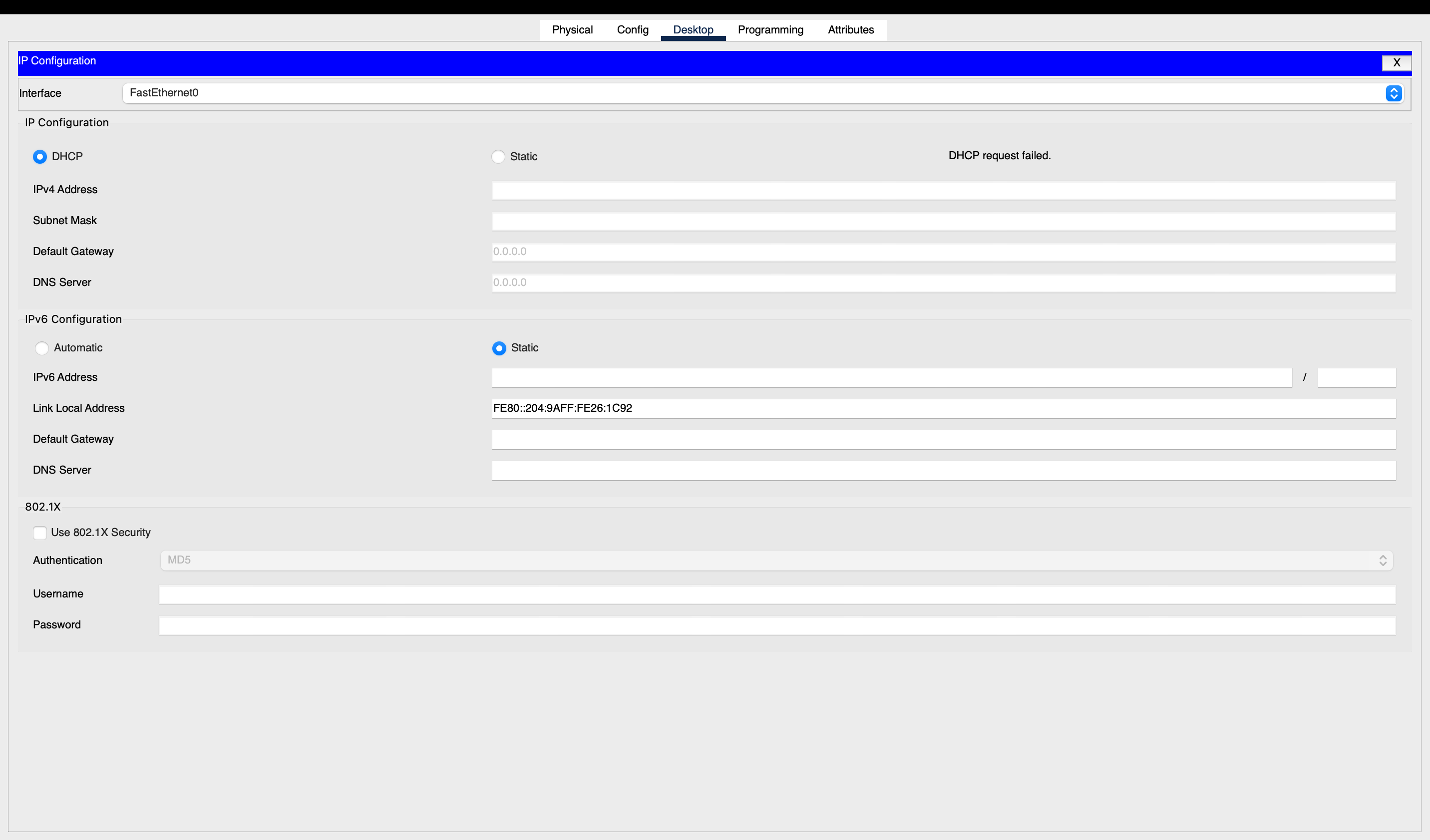
Several department PCs showed 169.254.x.x (APIPA) addresses even after VLANs and DHCP were correctly configured on the assumed access ports (Fa0/1, Fa0/2). The ports were configured correctly — but the PCs were not actually connected to them.
Task
Identify the actual physical port connections for each PC before changing any configurations.
Action
Used cable hover inspection in Packet Tracer combined with show interfaces status to map actual connections. Discovered PCs were physically wired to Gi0/1 or Gi0/2 instead of Fa0/1/Fa0/2. Configured the actual connected ports as access VLAN ports for the correct departments.
Result
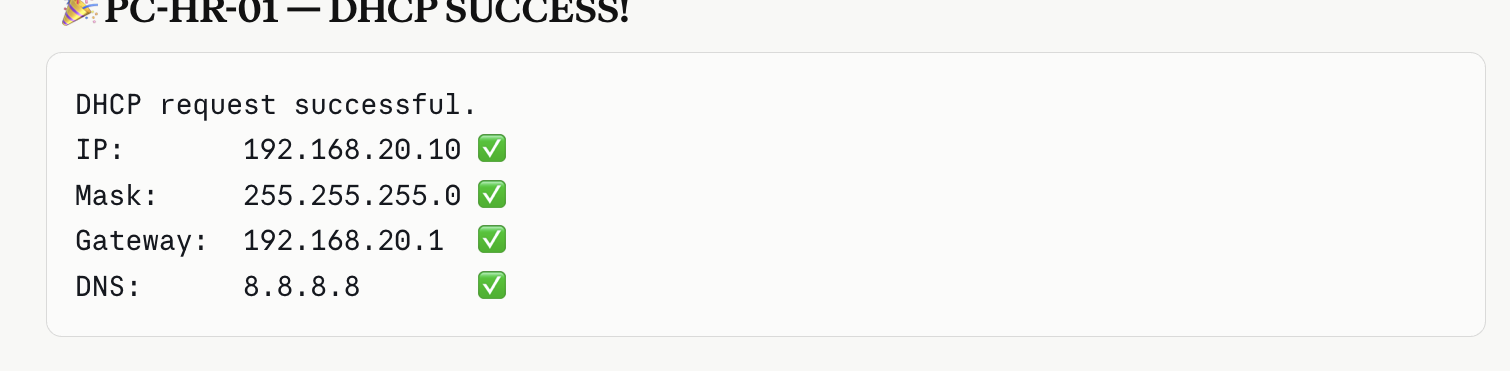
All affected PCs received correct DHCP leases from their department pools. Lesson reinforced: always verify physical connections before configuring access ports. Never assume the cable went where intended.
05
Medium Severity
Packet Tracer Default serverPool Overrides MGMT_POOL — Gateway Returns 0.0.0.0
Situation
VLAN 40 clients were successfully receiving DHCP leases but with a gateway of 0.0.0.0. Routing was failing. MGMT_POOL was configured correctly with gateway 192.168.40.1, but clients were not pulling from it.
Task
Identify which DHCP pool was winning the lease assignment and why the gateway was missing.
Action
Reviewed the DHCP pool table on the server. Found that Packet Tracer includes a built-in serverPool with no gateway configured, which was matching before MGMT_POOL. Neutralized serverPool by removing its network statement, leaving MGMT_POOL as the sole responder for the 192.168.40.0/24 range.
Result
VLAN 40 clients now pulled from MGMT_POOL with correct gateway 192.168.40.1. Routing restored. This issue is specific to Packet Tracer's default server behavior and would not occur on a real Cisco IOS DHCP server.
06
High Severity
Router Subinterface Configuration Stripped — Full Rebuild Required
Situation
DHCP relay continued to fail even after all switch issues were resolved. A show running-config on the router revealed only default interface configuration — all subinterfaces and ip helper-address statements were missing from the running config.
Task
Restore the complete router-on-a-stick configuration including all four subinterfaces, dot1Q encapsulation, gateway IPs, and DHCP helper addresses.
Action
Rebuilt G0/0.10 through G0/0.40 with correct encapsulation, IP addressing, and ip helper-address statements pointing to 192.168.40.2. Verified each subinterface with show ip interface brief before moving to the next.
Result
All four subinterfaces came up/up. DHCP relay functioned correctly across all VLANs. This rebuild confirmed the value of keeping a config reference — changes that look confined to one device can silently reset router state in Packet Tracer.
07
Medium Severity
STP PVID Inconsistency — Port Enters Blocking State After Native VLAN Correction
Situation
After native VLAN corrections, STP began logging a PVID inconsistency warning on one trunk link and placed the port in blocking state. The link appeared up physically but traffic was not forwarding.
Task
Identify and clear the STP inconsistency without disrupting the corrected VLAN configuration on the link.
Action
Ran show spanning-tree vlan 20 and identified the inconsistent port flag. Compared native VLAN configuration on both sides of the link — a residual mismatch remained on one switch after the earlier correction. Applied switchport trunk native vlan 1 consistently on both ends. The port recovered without a shutdown/no-shutdown cycle.
Result
STP PVID inconsistency cleared. Port returned to forwarding state and remained stable across all subsequent tests. Confirmed that STP will block a port on native VLAN mismatch even when the link appears physically healthy.
08
Low Severity
Management Access Unprotected — Telnet Open With No Line Restrictions
Situation
After the network was fully operational, a review of VTY line configuration showed that Telnet was enabled with no password, no access-class restriction, and SSH was not configured. Any device on any VLAN could manage the router and switches without authentication.
Task
Harden management access by enabling SSH, disabling Telnet on VTY lines, and restricting management access to VLAN 40 (Management subnet) only.
Action
Set hostname and domain name, generated RSA keys (crypto key generate rsa modulus 2048), enabled ip ssh version 2, created a local admin account, configured VTY lines to transport input ssh only, and applied an access-class ACL restricting source to 192.168.40.0/24.
Result
Telnet access disabled. SSH-only management confirmed. Management plane access restricted to VLAN 40. This hardening pattern applies directly to production Cisco environments and is commonly tested in Tier 2 support interviews.

Validation

Final checks confirmed every
segment was fully operational.

Validation focused on what a support engineer would actually prove before closing a ticket: correct DHCP leases, working gateways, trunk forwarding, and clean router subinterfaces.

UP/UP All router subinterfaces
4/4 DHCP pools active
8/8 Clients with valid leases
SegmentVLANExpected RangeGatewayPoolStatus
Finance10192.168.10.x192.168.10.1FINANCE_POOL✓ Validated
Human Resources20192.168.20.x192.168.20.1HR_POOL✓ Validated
Information Technology30192.168.30.x192.168.30.1IT_POOL✓ Validated
Management40192.168.40.x192.168.40.1MGMT_POOL✓ Validated

Command Reference

The show commands that
drove every diagnosis.

These are not a cheat sheet — they are the exact commands used in order during troubleshooting. The output of each command determined whether the issue was at Layer 2, Layer 3, or the DHCP server.

! Layer 2 — VLAN and trunk state
show vlan brief
show interfaces status
show interfaces trunk
show cdp neighbors
show cdp neighbors detail
show spanning-tree vlan 10
show spanning-tree vlan 20
! Layer 3 — router and DHCP
show ip interface brief
show running-config
show interfaces GigabitEthernet0/0.10
ping 192.168.40.2
ping 192.168.10.1

! Save config
write memory
copy running-config startup-config

Security Policy

ACL segmentation to enforce
real business access rules.

After connectivity was proven, a security layer was added to demonstrate how the design enforces business policy. HR should not be able to initiate traffic into the Finance VLAN. IT and Management remain reachable for support operations.

🚫
Deny HR (192.168.20.0/24) → Finance (192.168.10.0/24)
Applied inbound on G0/0.20 — blocks before routing
Permit All other traffic — IT, Management, inter-VLAN
Explicit permit any any at end of ACL
Cisco IOS ! Extended ACL — HR to Finance block
ip access-list extended BLOCK_HR_TO_FINANCE
deny ip 192.168.20.0 0.0.0.255 192.168.10.0 0.0.0.255
permit ip any any
!
! Apply inbound on HR subinterface — filters before routing
interface GigabitEthernet0/0.20
ip access-group BLOCK_HR_TO_FINANCE in
ACL placement reasoning: Applying inbound on the HR subinterface blocks unauthorized traffic before it enters the routed path. This is more efficient than filtering outbound on the Finance subinterface — it stops the packet at the source rather than allowing it to travel deeper into the network before being dropped.

Operational Hardening

Port security, SSH, and
management-plane restrictions.

Beyond connectivity and ACLs, a production-ready environment requires hardening at the access layer and management plane. These configurations demonstrate Layer 2 security awareness and controlled administrative access.

SSH Hardening — Management Access

SSH replaces Telnet for all VTY access. Management restricted to VLAN 40 only via access-class ACL.

IOS hostname R1
ip domain-name aurelian.local
crypto key generate rsa modulus 2048
ip ssh version 2
!
username admin privilege 15 secret StrongPass!
!
ip access-list standard MGMT_ACCESS
permit 192.168.40.0 0.0.0.255
!
line vty 0 4
login local
transport input ssh
access-class MGMT_ACCESS in

Port Security — Access Layer

Sticky MAC learning with violation restrict on department access ports — limits unauthorized devices at Layer 2.

IOS interface Fa0/1
switchport mode access
switchport port-security
switchport port-security maximum 2
switchport port-security violation restrict
switchport port-security mac-address sticky
switchport port-security aging time 30
!
! Validate with:
show port-security
show port-security interface Fa0/1

Configuration Backup and Rollback Discipline

Every stable config was saved and the /configs repository folder makes each device's final state reviewable, auditable, and reproducible.

configs/
├── router-config.txt
├── core-switch-config.txt
├── sw-finance-config.txt
├── sw-hr-config.txt
├── sw-it-config.txt
└── sw-mgmt-config.txt

Aurelian_Troubleshooting_Log.md
packet-tracer/
└── Aurelian_Enterprise_Network.pkt
Simulation note: These configurations are implemented as patterns in a Cisco Packet Tracer 8.x environment. Before applying equivalent controls in production, validate against the organization's security baseline, IOS feature support level, device models, and change-management process.

Validation Evidence

CLI output an interviewer
can verify on the spot.

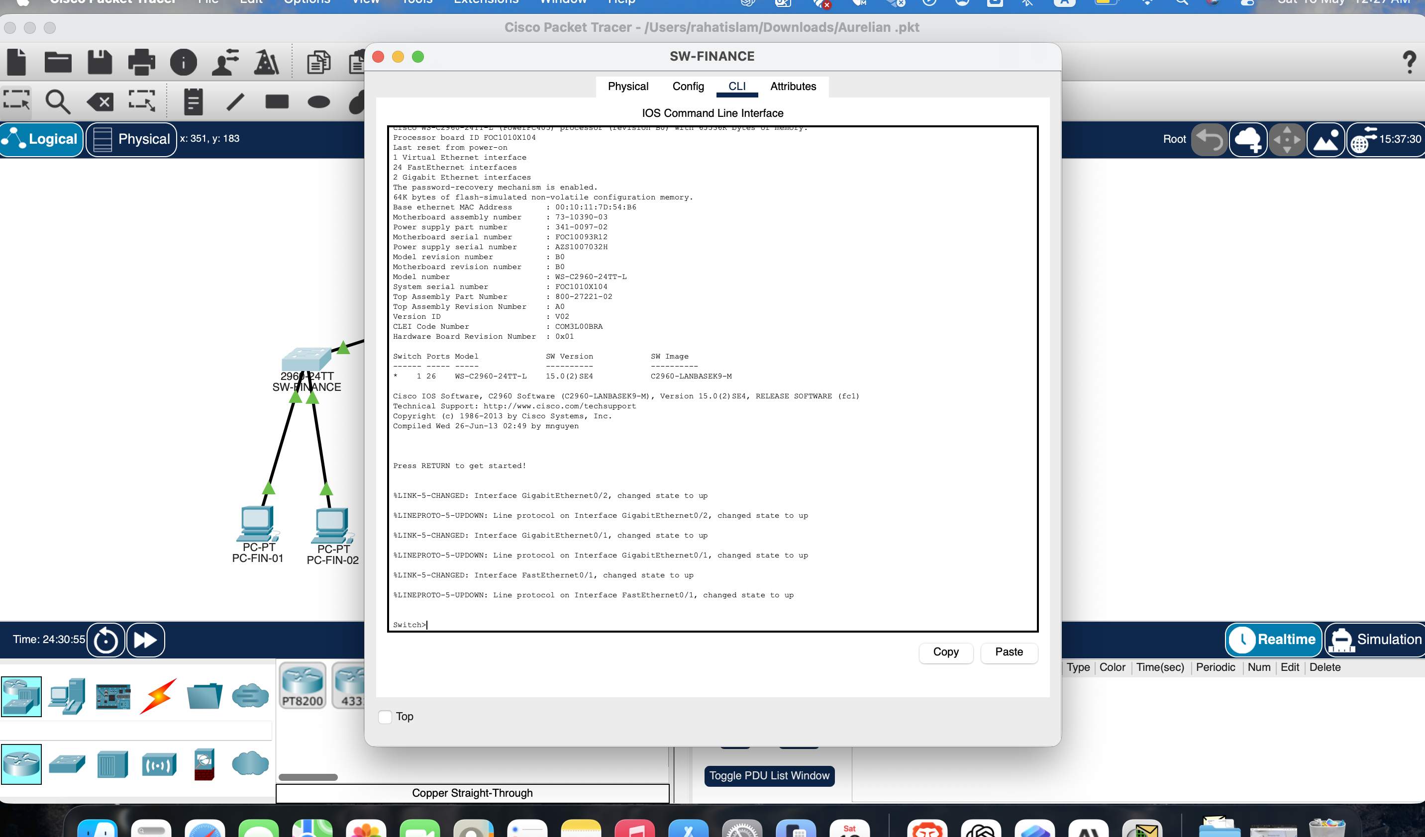
Every output below came directly from the live Packet Tracer session. These are the exact commands used to confirm each layer was working — not reconstructed after the fact.

Aurelian-RTR-01# show ip interface brief
Interface              IP-Address      OK?  Method  Status    Protocol
GigabitEthernet0/0     unassigned      YES  unset   up        up
GigabitEthernet0/0.10  192.168.10.1    YES  manual  up        up
GigabitEthernet0/0.20  192.168.20.1    YES  manual  up        up
GigabitEthernet0/0.30  192.168.30.1    YES  manual  up        up
GigabitEthernet0/0.40  192.168.40.1    YES  manual  up        up
GigabitEthernet0/1     unassigned      YES  unset   down      down
GigabitEthernet0/2     unassigned      YES  unset   down      down
✓ All four subinterfaces up/up — DHCP relay active on each gateway
SW-FINANCE# show interfaces trunk
Port        Mode     Encapsulation  Status    Native vlan
Fa0/1       on       802.1q         trunking  1

Port        Vlans allowed on trunk
Fa0/1       1-1005

Port        Vlans allowed and active in mgmt domain
Fa0/1       1,10,20,30,40

Port        Vlans in spanning tree forwarding state
Fa0/1       1,10,20,30,40
✓ All 4 VLANs forwarding — trunk active, native VLAN 1, no STP blocking
SW-FINANCE# show vlan brief
VLAN  Name                Status    Ports
1     default             active    Fa0/2, Fa0/3 ...
10    Finance             active    Gi0/1
20    HR                  active
30    IT                  active
40    Management          active
1002  fddi-default        active
1003  token-ring-default  active
1004  fddinet-default     active
1005  trnet-default       active
✓ VLAN 10 active — Finance PC on Gi0/1 confirmed in correct VLAN
SW-FINANCE# show interfaces status
Port    Name    Status       Vlan  Duplex  Speed  Type
Fa0/1           connected    trunk  auto    auto  10/100BaseTX
Gi0/1           connected    10     auto    auto  10/100BaseTX
Gi0/2           connected    10     auto    auto  10/100BaseTX
Fa0/2           notconnect   1      auto    auto  10/100BaseTX
Fa0/3           notconnect   1      auto    auto  10/100BaseTX
✓ Gi0/1 + Gi0/2 connected — physical ports verified before configuring access VLAN
Aurelian-RTR-01# ping 192.168.40.2
Type escape sequence to abort.
Sending 5, 100-byte ICMP Echos to 192.168.40.2,
timeout is 2 seconds:
!!!!!
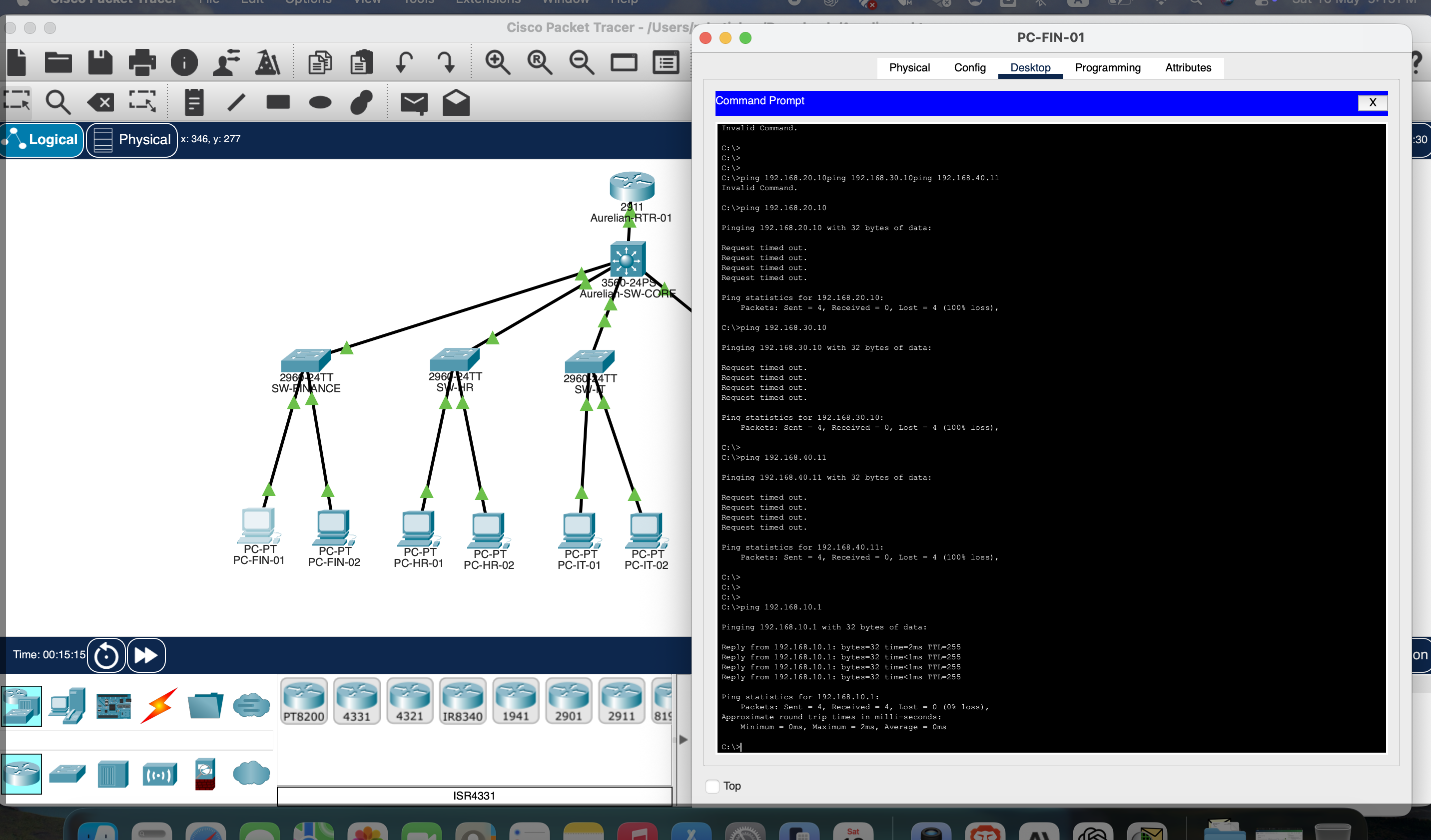
Success rate is 100 percent (5/5)
round-trip min/avg/max = 0/0/1 ms

! Router can reach DHCP server — relay path confirmed
✓ Router → DHCP server reachable — prerequisite for ip helper-address relay
SW-CORE# show interfaces trunk
Port    Mode   Encapsulation  Status    Native vlan
Fa0/1   on     802.1q         trunking  1  ← Router uplink
Fa0/2   on     802.1q         trunking  1  ← SW-IT
Fa0/3   on     802.1q         trunking  1  ← SW-FINANCE
Fa0/4   on     802.1q         trunking  1  ← SW-HR
Fa0/5   on     802.1q         trunking  1  ← SW-MGMT
✓ All 5 core uplinks trunking — dot1Q encapsulation applied, native VLAN 1 consistent
What This Demonstrates

Skills an interviewer
can verify on the spot.

This is not a lab-manual walkthrough. Every configuration decision was made under real debugging pressure — with actual error messages, wrong assumptions, and iterative diagnosis. Here is what a technical interviewer can take from this project.

Technical Skills Demonstrated

  • VLAN segmentation with 802.1Q trunking across access and core switches
  • Router-on-a-Stick: subinterface config, encapsulation, IP assignment
  • DHCP relay with ip helper-address crossing VLAN boundaries
  • Cisco 3560 vs 2960 encapsulation requirement — identified and corrected
  • Native VLAN mismatch — diagnosed via CDP, corrected on both trunk ends
  • Extended ACL with source/destination subnet matching — inbound direction
  • STP PVID inconsistency — read and resolved from console output
  • SSH hardening, port security, and management access restriction
  • Config backup discipline with write memory and exported configs

Diagnostic Methodology

  • Layered approach: physical → L2 trunk → L3 interface → DHCP server
  • show interfaces trunk — verify actual vs assumed trunk state
  • show ip interface brief — catch silent IP loss on "up/up" ports
  • show cdp neighbors — map physical port connections accurately
  • show spanning-tree vlan — eliminate STP as root cause first
  • show vlan brief — confirm which ports are in which VLAN
  • show interfaces status — identify connected vs notconnect ports
  • Physical cable verification before configuring — never assume topology
  • Every issue documented in STAR format: situation, task, action, result

Future Roadmap

How this lab evolves into
an advanced portfolio track.

The current build proves foundational enterprise skills. These extensions would demonstrate progressively advanced capability — each maps to a real interview topic or job requirement.

Network Resilience

Add HSRP for gateway redundancy, EtherChannel for uplink aggregation, and STP root bridge tuning to control the forwarding topology under link failure scenarios.

Dynamic Routing

Introduce OSPF to replace static default routes. Add a simulated branch office to demonstrate multi-site routing, area design, and route summarization.

Advanced Security

Expand ACL coverage with time-based rules and DHCP snooping. Add dynamic ARP inspection (DAI) and IP source guard to harden the access layer against spoofing.

Operations Visibility

Add syslog server configuration, SNMP-style monitoring notes, incident runbooks, and change-control documentation to simulate a production operations workflow.


Expanded screenshot